
Load bar plugs: getting the crimp right
Quick answer
- Cat6 requires a load bar to organise conductors into staggered rows before crimping, unlike Cat5e's simple single-row layout.
- Use T568B for new Australian commercial installations, and always test the finished termination before calling the job done.
- Access Communications stocks the full range of Cat6 load bar plugs and termination tools.
Terminating Cat6 cable correctly is the difference between a clean Gigabit link and a network that's plagued by intermittent dropouts, slow speeds and crosstalk. Unlike Cat5e, Cat6 requires a load bar (or equivalent wire-organising mechanism) to manage the thicker 23 AWG conductors and meet the stringent crosstalk performance of the standard. This guide covers which load bar plug to choose, the tools required, the correct wiring sequence for Australia, step-by-step termination, and how to identify the three historical load bar versions still found in the field.
Why Cat6 needs a load bar
Cat6 cable uses 23 AWG conductors, which are noticeably thicker than the 24 AWG used in Cat5e. If you tried to line all eight Cat6 conductors up in a single row inside the plug body the way Cat5e plugs do, the wires would not physically fit. More importantly, Cat6 must meet a much higher crosstalk specification at 250 MHz bandwidth, and that is impossible with the simple single-row arrangement used for Cat5e.
A load bar solves both problems. It organises the eight conductors into two staggered rows (typically 4 over 4, or 6 over 2 depending on the plug version) before they enter the plug body. This staggered arrangement physically separates the pairs from each other at the termination point, dramatically reducing near-end crosstalk (NEXT) and far-end crosstalk (FEXT), which is what allows the finished link to meet Cat6 performance.
For more on telling Cat5e and Cat6 plugs apart, see our visual guide to Cat5 and Cat6 plugs. If you're deciding between a load bar plug and a pass-through plug for a job, see our pass-through RJ45 termination walkthrough for the alternative approach.
Which load bar plug should you use?
Access stocks several load bar plug options, each suited to different applications.
| Plug type | Best for | Access SKU |
|---|---|---|
| Cat6 standard 2-piece (load bar) | Standard Cat6 UTP terminations, patch leads and field installs where time is not critical | P2176UB family |
| Cat6/6a shielded 2-piece | Bulk shielded patch lead production | P2178UJ |
Looking for a pass-through (Quick Term) plug instead? See our pass-through RJ45 termination walkthrough.
Tools you'll need
For a proper Cat6 termination with a load bar plug, you need three core tools plus a tester to verify your work.
- Cable stripper: A T0033 cable stripper sets the correct strip length and removes the outer jacket cleanly without nicking the inner conductors.
- Modular crimp tool: A T0019 8P8C ratchet crimp tool applies the correct compression force to seat the contacts onto the conductors and lock the strain relief onto the cable jacket.
- Wire cutters or flush cutters: Clean, straight cuts on the conductors are essential. Diagonal cutters work but flush cutters give the best result.
- LAN cable tester: A T0042001 LAN cable tester verifies continuity and the wiring sequence. Skipping this step is the most common cause of installer callbacks.
Optional but recommended: strain relief boots in matching colour, slid onto the cable before terminating.
Australian wiring sequence: T568A or T568B?
The two standard wiring patterns for terminating an RJ45 plug are T568A and T568B. They differ only in that the orange and green pairs are swapped. Both deliver identical Ethernet performance.
For new Australian commercial installations, use T568B. Most patch panels, keystones, jacks and factory-terminated patch leads sold through Australian trade channels are wired T568B by default. If a product specification does not state otherwise, assume T568B. The most important rule is consistency: both ends of any single cable run must use the same standard.
For a full side-by-side comparison and the reasoning behind the AU commercial default, see our RJ45 wiring guide (T568A and T568B).
| Pin | T568A colour | T568B colour |
|---|---|---|
| 1 | Green/White | Orange/White |
| 2 | Green | Orange |
| 3 | Orange/White | Green/White |
| 4 | Blue | Blue |
| 5 | Blue/White | Blue/White |
| 6 | Orange | Green |
| 7 | Brown/White | Brown/White |
| 8 | Brown | Brown |
Step-by-step termination: Cat6 load bar plug (P2176UB)
The following steps cover the standard 2-piece load bar plug (P2176UB family). If you have an older Access load bar plug with a slightly different geometry, see the three historical versions further down this page.
- Slide the boot on first. If you are using a strain relief boot, slide it onto the cable now. Boots cannot be added after the plug is crimped.
- Strip approximately 20mm of outer jacket. Use the T0033 cable stripper. The adjustable blade is set to score the jacket without nicking the inner conductors.
- Cut the rip cord and any cross-web divider. Trim both flush with the end of the jacket.
- Untwist the pairs and straighten each conductor. Untwist each pair back to the jacket. Do not nick or kink the conductors.
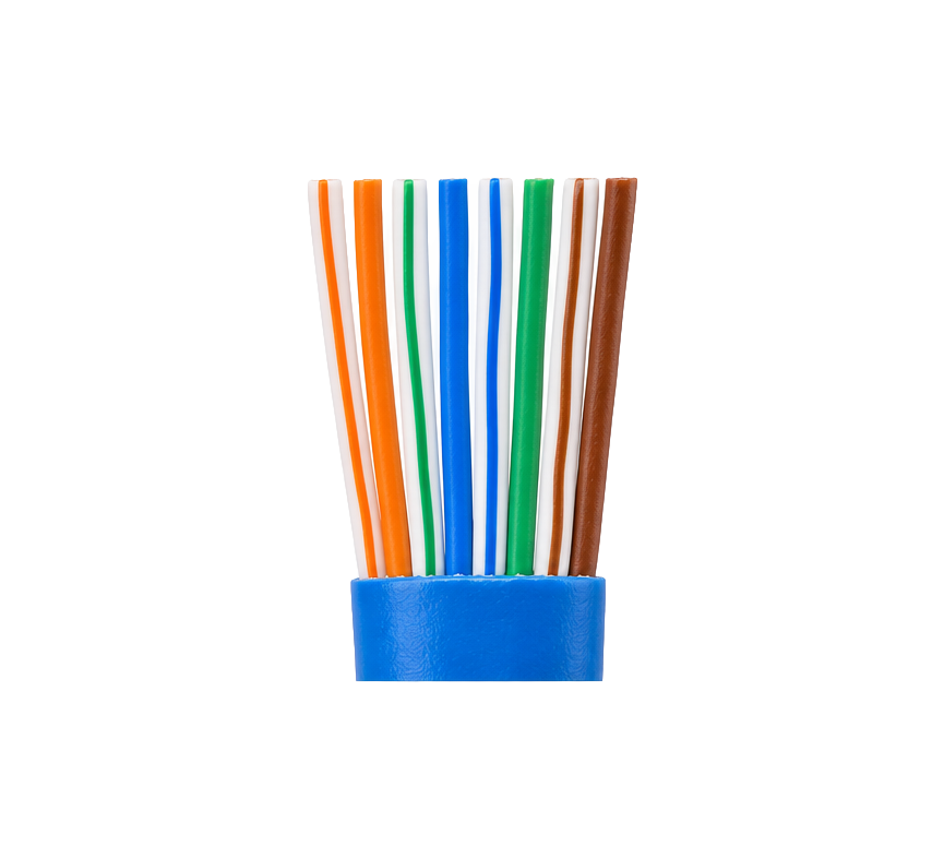
- Arrange the conductors in the correct sequence. Fan the eight conductors out and arrange them in T568B order.
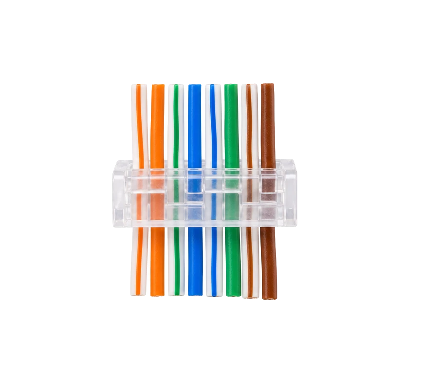
- Trim the conductors to an even 8mm. Hold the conductors flat and cut them all to the same length with flush cutters. A straight, even cut is essential for the plug contacts to seat properly.
- Insert the conductors into the load bar. Orient the load bar with the staggered rows facing the correct direction. Push each conductor into its corresponding hole until it reaches the end.
- Push the load bar fully against the cable jacket. There should be no exposed conductor between the jacket and the load bar.
- Insert the cable and load bar into the plug body. Push the assembly into the plug body until the load bar reaches the front of the plug.
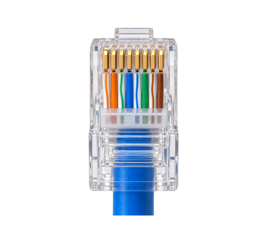
- Verify the conductors are fully seated. Look at the front of the plug. Every conductor should be visible right at the end of its channel, with no gap.
- Crimp the plug with the T0019 ratchet crimp tool. Insert the plug into the 8P8C die. Squeeze the handles fully closed until the ratchet releases.
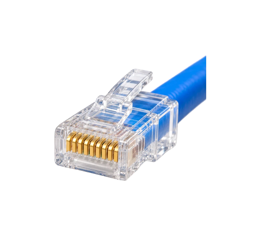
- Check the contacts. Every gold contact should be pressed down level. If any contact is sitting higher than the others, the connection may be unreliable.
- Slide the boot up and snap it onto the plug.
- Test the termination. Use the T0042001 LAN cable tester to verify continuity and the wiring sequence. Test both ends. Mark the cable as tested and label both ends with the run identifier.
Identifying the three historical load bar versions
Access has supplied three different versions of the Cat6 standard 2-piece plug over the years. The plug body and process are essentially the same, but the load bar geometry differs. For the current P2176UB plug, use the step-by-step instructions above.
Version 1: blocked-end load bar

The first version had a load bar in which the conductor holes were blocked at the front. Conductors could only be inserted partway through. The conductors must be trimmed to exactly 8mm before insertion, because they cannot be cut after the load bar is in place.
Key step difference: Trim the conductors to 8mm BEFORE inserting into the load bar (step 6 happens before step 7).
For the original 2003 instruction sheet, see Version 1 instructions (PDF).
Version 2: pass-through load bar

The second version introduced pass-through holes. Conductors are inserted all the way through the load bar and trimmed flush after the load bar is positioned. This is forgiving and is the same approach used by today's P2176UB. Note this is a load bar with pass-through holes, not the same as a pass-through (Quick Term) plug, see our pass-through termination walkthrough for that separate product type.
Key step difference: Insert the conductors first, then trim flush after the load bar is pushed against the jacket.
For the original 2003 instruction sheet, see Version 2 instructions (PDF).
Version 3: load bar with legs

The third version added two protruding "legs" at the front of the load bar. The legs locate the bar precisely against the cable sheath so the end of the legs sits flush with the end of the jacket, ensuring consistent geometry.
Key step difference: When pushing the load bar against the jacket, the legs should sit flush with the cable sheath end.
For the original 2006 instruction sheet, see Version 3 instructions (PDF).
Common termination mistakes
- Untwisting pairs too far back. Each pair should remain twisted as close to the load bar as possible. Untwisting more than 13mm pushes Cat6 performance into Cat5e territory.
- Cutting conductors at uneven lengths. If the conductors are not all exactly the same length, some contacts will not pierce the insulation properly. Always trim them flat together.
- Nicking conductors during stripping. A blade set too deep cuts through the conductor insulation and into the copper. Adjust the T0033 to score only the outer jacket.
- Not seating the conductors fully against the plug end. If a conductor sits even 1mm short of the end of the plug, the contact will not pierce the insulation correctly. Always verify before crimping.
- Crimping too early. If the load bar is not fully inserted into the plug body, the strain relief will not engage the cable jacket properly. Pull-test the finished plug.
- Mixing T568A and T568B at opposite ends. This creates a crossover cable, which is almost never wanted for modern Ethernet. Use the same wiring at both ends.
- Skipping the test. Untested terminations are the single biggest source of installer callbacks. A 30-second test with a T0042001 LAN tester saves hours of troubleshooting later.
Frequently asked questions
What is a load bar in a Cat6 plug?
A load bar is a small plastic component that organises the eight conductors of a Cat6 cable into two staggered rows before they enter the plug body. It is required for Cat6 plugs because the thicker 23 AWG conductors will not fit in a single row, and because the staggered arrangement is what enables the Cat6 plug to meet the higher crosstalk performance specification of the standard.
Can I use a Cat5e plug on Cat6 cable?
Physically you may be able to crimp a Cat5e plug onto Cat6 cable, but the Cat6 conductors are thicker than the Cat5e plug is designed for, so the crimp will be unreliable. More importantly, you will downgrade the entire link to Cat5e performance. Always match the plug to the cable.
What strip length should I use for a Cat6 load bar plug?
Approximately 20mm of outer jacket for the Access P2176UB plug family. Trim the individual conductors to a final length of 8mm so they extend cleanly to the end of the plug.
Should I use T568A or T568B for Australian Cat6 installations?
For new Australian commercial installations, use T568B. Most patch panels, keystones, jacks and factory-terminated patch leads sold through Australian trade channels are wired T568B by default. T568A is generally only required where existing wiring uses it, or where US federal specifications apply. The most important rule is consistency: both ends of any single cable must use the same standard.
What's the difference between the three Cat6 load bar versions?
Access has supplied three versions over the years. Version 1 had blocked load bar holes requiring conductors to be pre-trimmed to 8mm. Version 2 introduced pass-through holes allowing conductors to be trimmed after insertion. Version 3 added locating legs at the front of the load bar for consistent positioning against the cable sheath. All three terminate the same finished plug and use the same crimp tool.
How do I know my Cat6 termination meets the standard?
Visually verify that the conductors are fully seated, that all contacts are flush with the top of the plug, and that the strain relief is engaged with the cable jacket. Then test with a LAN cable tester to confirm continuity, wiring sequence and absence of opens, shorts or split pairs. For mission-critical installs, a Cat6 certification tester (such as a Fluke DSX) measures NEXT, return loss and insertion loss against the standard.
Looking for pass-through (Quick Term) plug information instead? See our pass-through RJ45 termination walkthrough, covering tools, wiring, step-by-step termination, TIA-568 compliance and PoE safety for that plug type.
Your Project, Perfected. That's The Access Advantage.
- Expert Local Support, Since 1973: Don't waste time with guesswork. Our experts have seen it all and are ready to provide the right solution, right now. Your success is our business.
- Your Specs, Your Brand, Our Build: Off-the-shelf not cutting it? We specialise in building custom cables and assemblies to your exact specifications, branded for your business. Let's create it together.
- Guaranteed for Life: Buy it once. Trust it forever. Our products are backed by a limited lifetime warranty, so you can invest in quality with zero risk. *Warranty excludes third-party brands such as HALO and UPS.
Let's get your project started.
Talk to an expert today for a custom quote or browse the solutions most relevant to your search.