How to use this guide
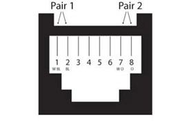
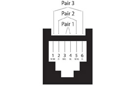
Each diagram on this page shows a modular socket viewed from the front. Use the identification key below to match the colours on pins 1 and 2 of an unknown socket to the correct scheme, then jump to the full pinout diagram for detail.
This page covers all six schemes encountered in Australian structured cabling, including legacy schemes still found in older commercial and institutional buildings. For the T568A vs T568B decision guide and AU standard recommendation, see our RJ45 Wiring (T568A and T568B) guide.
This page covers all six schemes encountered in Australian structured cabling, including legacy schemes still found in older commercial and institutional buildings. For the T568A vs T568B decision guide, pinout tables with Tip and Ring pair assignments, and the AU standard recommendation, see our RJ45 Wiring (T568A and T568B) guide.
Quick field identification key
Look at pins 1 and 2 on the socket. Match the colours to identify the scheme.
| Pin 1 colour | Pin 2 colour | Then check | Likely scheme |
|---|---|---|---|
| Orange/White | Orange | Standard 8-conductor socket | T568B (most common in AU) |
| Green/White | Green | Standard 8-conductor socket | T568A |
| Blue/White | Blue | Check pins 7 and 8: if Orange/White and Orange | TP-PMD |
| Blue/White | Blue | Check pins 7 and 8: if empty or unused | 10Base-T |
| Green/White | Orange/White | Centre pairs only, 6-conductor | USOC (telephone) |
| Pins 1 and 2 empty | Pins 1 and 2 empty | Active pins are 3, 4, 5, 6 only | Token Ring |
T568B wiring
T568B is the standard for new commercial and residential data installations in Australia. If you are looking at a socket installed in the last 20 years by a registered cabler, it is almost certainly T568B. All Access Communications patch panels, keystones, and factory-terminated patch leads are wired T568B by default.
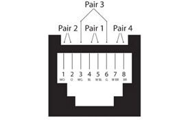
| Pin | Colour |
|---|---|
| 1 | Orange/White |
| 2 | Orange |
| 3 | Green/White |
| 4 | Blue |
| 5 | Blue/White |
| 6 | Green |
| 7 | Brown/White |
| 8 | Brown |
T568A wiring
T568A swaps the orange and green pairs compared to T568B. It is encountered on older Australian installations, some residential wiring, and sites that followed US government specifications. If you are working on an existing T568A installation, match T568A throughout. Do not mix T568A and T568B on the same cable run.
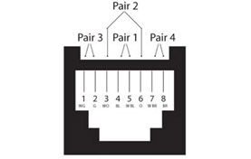
| Pin | Colour |
|---|---|
| 1 | Green/White |
| 2 | Green |
| 3 | Orange/White |
| 4 | Blue |
| 5 | Blue/White |
| 6 | Orange |
| 7 | Brown/White |
| 8 | Brown |
Legacy wiring schemes
The schemes below are no longer used in new installations but are still encountered when working on older commercial, institutional, and government infrastructure. Each entry includes the context you need to recognise and deal with it on site.
10Base-T wiring
10Base-T was the original 10 Mbps Ethernet standard (IEEE 802.3). It used only two of the four pairs: pins 1, 2, 3, and 6 carry data; pins 4, 5, 7, and 8 are unused. It is found in older office buildings and schools where the cabling has not been replaced since the 1990s. The socket will typically pass a modern cable tester but fail on pair count. Re-terminating to T568B using all four pairs is required before the run will support Gigabit or PoE.
| Pin | Colour |
|---|---|
| 1 | Blue/White |
| 2 | Blue |
| 3 | Orange/White |
| 6 | Orange |
Token Ring wiring
Token Ring was IBM's LAN technology running at 4 Mbps or 16 Mbps, displaced by Fast Ethernet through the late 1990s. It used pins 3, 4, 5, and 6 only, leaving pins 1, 2, 7, and 8 unused. Token Ring infrastructure is occasionally found in older manufacturing, banking, and government sites that were never fully rewired. The pin assignment is distinctive: if pins 1 and 2 are empty and 3 through 6 are active, Token Ring is the most likely explanation.
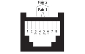
| Pin | Colour |
|---|---|
| 3 | Orange/White |
| 4 | Blue |
| 5 | Blue/White |
| 6 | Orange |
TP-PMD wiring
TP-PMD (Twisted Pair Physical Medium Dependent) was the copper cabling standard for FDDI, a 100 Mbps token-ring network technology from the early 1990s used mainly in campus backbones and government facilities. It used an unusual pin assignment: pins 1, 2, 7, and 8, which places both active pairs at the outer edges of the connector. This is the easiest legacy scheme to misread because pins 1 and 2 look like 10Base-T until you notice pairs on pins 7 and 8 as well. FDDI infrastructure is rare but does appear in older university campuses and government buildings.
| Pin | Colour |
|---|---|
| 1 | Blue/White |
| 2 | Blue |
| 7 | Orange/White |
| 8 | Orange |
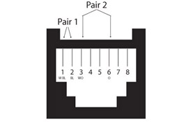
USOC wiring
USOC (Universal Service Order Code) is a US telephone wiring standard that predates structured data cabling. It uses a centre-outward pair assignment where pairs nest from the middle pins outward, rather than the sequential pair assignment used in T568A and T568B. In Australia it appears in older office buildings wired by US-trained contractors or using US-sourced telephone hardware. USOC is not used for data. If you find a 6-conductor socket with blue pairs at pins 3 and 4, it is telephone wiring and should not be used for Ethernet without full re-termination.
| Pin | Colour |
|---|---|
| 1 | Green/White |
| 2 | Orange/White |
| 3 | Blue |
| 4 | Blue/White |
| 5 | Orange |
| 6 | Green |
Frequently asked questions
How do I identify which wiring scheme is on an existing wall socket?
Look at pins 1 and 2. If they are Orange/White and Orange, the socket is T568B. If they are Green/White and Green, it is T568A. If they are Blue/White and Blue, check pins 7 and 8: if those are also wired, it is TP-PMD; if they are empty, it is likely 10Base-T. If pins 1 and 2 are Green/White and Orange/White, it is USOC telephone wiring. If pins 1 and 2 are empty and only the middle four pins are active, it is Token Ring. Use the identification key at the top of this page as a quick reference on site.
Can I use a 10Base-T socket for Gigabit Ethernet?
Not without re-terminating. 10Base-T only uses two of the four pairs. Gigabit Ethernet (1000Base-T) requires all four pairs, and PoE requires all four pairs for power delivery. If the cable itself is Cat5e or better and has all four pairs run back to the patch panel, re-terminating the socket to T568B using all four pairs will bring it up to Gigabit standard. If the cable is only two-pair, the run needs to be replaced entirely.
I found a socket with an unusual pin assignment. Could it be something not on this list?
Possibly. Some older proprietary systems (early IP phone infrastructure, older building management systems, certain nurse call wiring) used non-standard pinouts specific to that equipment. If the pattern does not match any scheme on this page, the best approach is to trace the cable back to the source equipment and check that manufacturer's documentation. Do not assume it is safe to repurpose without verifying.
What is the difference between a socket-view diagram and a plug-view diagram?
A socket-view diagram shows the socket from the front, as you would see it mounted in a wall plate. Pin 1 is on the left. A plug-view diagram shows the plug from the front with the locking tab facing down, which reverses the pin order. This page uses socket-view diagrams throughout. The RJ45 Wiring guide uses plug-view diagrams. If you are cross-referencing between the two, note that pin 1 appears on opposite sides depending on which view is shown.
Why does Australian wiring use T568B rather than T568A?
Australian commercial cabling practice has defaulted to T568B for many years, driven primarily by the hardware available through Australian trade channels. The majority of patch panels, keystones, jacks, and factory-terminated patch leads sold in Australia are manufactured to T568B. While older versions of the Australian cabling standard referenced T568A, the practical reality of the supply chain means T568B is what registered cablers work with daily. For new installations, T568B is the correct choice unless the existing infrastructure already uses T568A throughout.
If I find Token Ring or TP-PMD sockets, should I rewire them?
Only if the run is being brought into active use. Legacy sockets that are capped off and not connected to anything active can be left in place. If a run needs to carry modern Ethernet, the socket needs to be re-terminated to T568B and the cable tested to confirm it has all four pairs intact and meets the category rating required for the application.
Your Project, Perfected. That's The Access Advantage.
- Expert Local Support, Since 1973: Don't waste time with guesswork. Our experts have seen it all and are ready to provide the right solution, right now. Your success is our business.
- Uncompromising Aussie Quality: We live and breathe quality. From rigorous testing to official Australian certification, we guarantee every product we sell is built to perform and built to last.
- Your Specs, Your Brand, Our Build: Off-the-shelf not cutting it? We specialise in building custom cables and assemblies to your exact specifications, branded for your business. Let's create it together.
- Guaranteed for Life: Buy it once. Trust it forever. Our products are backed by a limited lifetime warranty, so you can invest in quality with zero risk. *Warranty excludes third-party brands such as HALO and UPS.
- Innovation That Keeps You Ahead: The tech landscape is always changing, and so is our catalogue. We ensure you always have access to the latest, most reliable solutions on the market.
Let's get your project started.
Talk to an expert today for a custom quote or browse the solutions most relevant to your search.