
Page 64 - Access Catalog 10
P. 64
63
REFERENCE
Modular Plug Termination Recommendations
• Always use a modular plug with the correct contacts for stranded conductors or solid conductors.
• Do not terminate flat cord plugs onto round cord & vice versa.
• Avoid plugging 6 position plugs into 8 position sockets where possible.
• Use quality tools for crimping modular plugs.
• Avoid RJ11, RJ45 Terminology to avoid confusion.
• Ensure plugs with suitable grade of gold plating are used.
• Avoid excessive bending or squashing of data cable jackets.
• Use plug boots to provide extra strain relief.
Note
We recommend adoption of 8P8C, 6P4C terminology when describing modular plugs and jacks. This is a definite way to avoid confusion between similar plugs.
The codes RJ11, RJ12, RJ45 and other RJ (Registered Jack) numbers actually specify various wiring configurations used in the USA,
not actual Plug or Jack types.
Straight-through and Cross-over Cords Modular Cords
Flat modular cords can be wired in either straight-through or cross-over configuration. Cross-over wiring is most commonly used for connection of equipment such as telephones, modems, faxes and terminals to a modular wall outlet. However, voice applications will usually tolerate either configuration. Data equipment may use either straight-through or cross-over depending on the equipment’s specifications. Accessories such as couplers and double adaptors are available in straight-through or cross-over models.
Flat Modular Cord Wiring Configurations
Straight-through Polarity
Cross-over Polarity
Pin 1
Pin 1
Pin 1
Pin 8
Pin 3
Pin 3
Pin 3
Pin 6
Pin 5
Pin 5
Pin 5
Pin 4
Pin 7
Pin 7
Pin 7
Pin 2
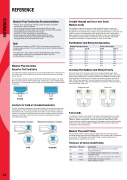
Modular Plug Variations Round or Flat Cord Entry
2 variations of modular plug exist to accommodate either Flat or Round cord. The lower face of the cord entry on the rear of the plug body can be either Flat or Round.
The round type should always be used when terminating Category 5 or other Round cords to ensure that the jacket and conductors are not crushed during termination. Flat cord plugs must be used to ensure adequate cord strain relief of flat cord.
Round Flat Contacts for Solid or Stranded Conductors
The IDC (Insulation Displacement Contact) section of the Gold contacts can be designed for either Solid conductors or Stranded conductors. Plugs for solid wires have a 3 pronged contact which forks over the Solid conductor whilst the contacts for stranded conductors have 2 spikes which penetrate between the strands. Failure to use to correct contact type will result in unreliable terminations.
End A
Pin 2 Pin 4 Pin 6 Pin 8
End B
Pin 2 Pin 4 Pin 6 Pin 8
End A
Pin 2 Pin 4 Pin 6 Pin 8
End B
Pin 7 Pin 5 Pin 3 Pin 1
Checking Flat Modular Cord Wiring Polarity.
Hold both ends of the modular cord with the plugs alongside each other. Ensure that the gold contacts of both plugs are facing you and the cord from each plug is leading down. The gold contacts are numbered from left to right with the plugs in this orientation. Compare the colour sequence from left to right. If the colours appear in the same sequence on both plugs, the cord is wired straight-through. If the colour sequence is reversed on the second plug, the cord is wired cross-over.
Patch Cords
The majority of patch cords used for connections between jacks on a patch panel or from a PC or terminal to a wall outlet are wired straight-through in T568A to T568A configuration. Cross-over cords are used to daisy-chain switches/hubs or for direct connection of 2 computer network interface cards. Cross-over cord wiring is T568A to T568B with the wiring of the green and orange pairs being transposed.
Modular Plug Gold Plating
The contacts used in modular plugs are gold plated and the gold plating thickness affects the electrical characteristics of the contact and it’s resistance to corrosion. The thickness of the Gold Plating is usually measured in μ” (Microinches) or sometimes in microns.
Thickness of Contact Gold Plating
Microinch
Microns
Comments
Solid
Stranded
Not recommended. Sometimes used on poor quality or unapproved telephones.
6μ” 0.15μm
15μ”
0.38μm
The minimum quality for satisfactory voice connections. Unsuitable for data.
30μ” 0.76μm Satisfactory for voice connections and low speed data only.
50μ”
1.27μm
Provide reliable voice & data connection (when terminated correctly).
REFERENCE
